2. School of Astronautics, Beihang University, Beijing 100191, China
At present, a large number of researchers worldwide are engaged in the numerical simulation of gas-dynamic processes in solid-propellant rocket motors (SPRMs). This fact can be confirmed by, for example, a large number of reports on this topic at the last International Astronautical Congresses. At the same time, the researchers pay attention to a wide range of problems.
Simulation was carried out taking into account the chemical reactions occurring during solid-propellant combustion[1]. The features of processes in metallized fuels were studied[2]. The currents of two-phase flows in SPRM channel were considered[3]. Simulation was carried out taking into account the burning surface change and the volume of SPRM chamber owing to propellant burn[4]. Numerical analyses of the flow instability in a segmented solid rocket motor were carried out[5~7]. The partial vortex shedding phenomenon observed in SPRM is investigated by applying a local non-parallel hydrodynamic stability approach, and large eddy simulations were performed on two different configurations and compared with the results obtained by the LNP method based on spatial evolution of the flow instabilities[8, 9]. Multiphase flow computations were performed including three-way coupling between phases, conservative coupling approach, and full heat release for the burning mechanisms[10]. Similarly, Numerical simulations of the multiphase features in SRM's internal flow were performed[11]. A 2D adiabatic micro-scale combustion model was built based on the computational software Fluent and reduced chemical kinetic mechanism[12]. For a new concept of solid propellant microthruster, a simulation was performed using MEMS technologies[13].
However, the use of numerical simulation while designing SPRM is constrained by the fact that such calculations require much time(solving a three-dimensional problem of a steady turbulent flow of combustion products takes several hours of the calculation time). The author does not know the works devoted to the study of the influence of calculation model parameters on calculation time in relation to the simulation processes in SPRM combustion products.
This research deals with the investigation results how to reduce the calculation time(naturally, without reducing the accuracy of the data obtained). The influence of such factors as the use of numerical methods of high accuracy order, the reduction in the spatial dimension of the problem, and the use of the physical features of processes in SPRM chamber while constructing a calculation model are considered.
Since the research is of methodical nature, all calculation models are made on the basis of the equations of nonviscous non-heat-conducting compressible gas and the power law of solid propellant combustion
| $ \frac{{{\rm{d}}e}}{{{\rm{d}}t}} = {u_1}{p^b} $ | (1) |
Here e-a thickness of burned propellant, p-pressure of combustion products, u1, b-empirical constants.
In all the problems solved below, the gas parameters in SPRM chamber before starting are set as the initial data before the start of its operation. The boundary data is set as follows: the flow parameters at the cut of a nozzle are defined by the solution of the Riemann problem (disintegration of discontinuities); impermeability conditions are set on the solid wall; the inflows of mass, impulse and energy dealing with the calculation region of combustion products are set on the boundary of burning solid propellant.
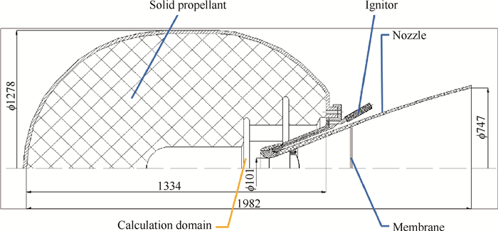
2 The use of numerical methods of high accuracy orderObviously, the use of numerical methods of high accuracy order (higher than the second) requires more arithmetic operations and, correspondingly, more time to perform calculations than using methods of low accuracy order. However, it is shown[14] that in order to achieve the same error value, methods of high accuracy order require less points while performing the sampling of the calculation region and less time for calculations(while solving one-dimensional nonstationary problems of gas dynamics, this gain is 2.5 times on the number of points and 1.5 times on the calculation time). In the present paper, we try to check on this statement by solving the problem of the numerical simulation of SPRM launch process of Star 48V. The general configuration of the simulated device is shown in Fig. 1.
|
Fig. 1 General configuration of SPRM star 48V(mm) |
In this engine, mixed propellant is used(18% Al, 11% PClA, 71% NTPV). Its combustion products have the following thermodynamic properties: heat capacity at constant pressure Cp=1758J/(kg·K), gas constant R= 255J/(kg·K), combustion products temperature Tcp = 3539K, ignition temperature Tign =910K.
As the initial system of equations for constructing a calculation model, we use a system of equations for the dynamics of nonviscous non-heat-conducting gas presented in a conservative form in a non-orthogonal axially symmetric system of coordinates
| $ \begin{array}{*{20}{c}} {\frac{{\partial {\mathit{\boldsymbol{U}}_1}}}{{\partial t}} + \frac{{\partial {\mathit{\boldsymbol{F}}_1}}}{{\partial \xi }} + \frac{{\partial {\mathit{\boldsymbol{G}}_1}}}{{\partial \eta }} = {S_1}}\\ {{\mathit{\boldsymbol{U}}_1} = \frac{\mathit{\boldsymbol{U}}}{J},{\mathit{\boldsymbol{S}}_1} = \frac{\mathit{\boldsymbol{S}}}{J}}\\ {{\mathit{\boldsymbol{F}}_1} = \frac{1}{J}\left( {{\mathit{\boldsymbol{F}}_1}{\xi _x} + \mathit{\boldsymbol{G}}{\xi _r}} \right),{\mathit{\boldsymbol{G}}_1} = \frac{1}{J}\left( {{\mathit{\boldsymbol{F}}_1}{\eta _x} + \mathit{\boldsymbol{G}}{\eta _r}} \right)}\\ {\mathit{\boldsymbol{U}} = \left( \begin{array}{l} \rho \\ \rho u\\ \rho v\\ E \end{array} \right),\mathit{\boldsymbol{F}} = \left( \begin{array}{l} \rho u\\ \rho {u^2} + p\\ \rho vu\\ uH \end{array} \right),\mathit{\boldsymbol{G}} = \left( \begin{array}{l} \rho v\\ \rho uv\\ \rho {v^2} + p\\ vH \end{array} \right),\mathit{\boldsymbol{S}} = - \frac{1}{r}\left( \begin{array}{l} \rho v\\ \rho uv\\ \rho {v^2}\\ vH \end{array} \right)} \end{array} $ | (2) |
Here (x, r) are the coordinates in a cylindrical system of coordinates, (ξ, η) are the coordinates in a nonorthogonal axially symmetric system of coordinates, J is Jacobian of the transition between systems of coordinates, ρ, p, H, E-are respectively the density, pressure, enthalpy and total gas energy, u, v are the projections of the velocity vector on the axis of the cylindrical coordinate system.
The system of equation(2) is closed by the following thermodynamic formula
| $ E = \rho \left( {\varepsilon + \frac{{{u^2}}}{2}} \right),H = \rho h = E + p,p = \left( {k - 1} \right)\rho \varepsilon ,h = {C_p}T,\varepsilon = {C_v}T $ | (3) |
The mapping (x, r)→(ξ, η) is presented in such a way that the number of kinks of the boundary of the calculation domain in the plane (ξ, η) is not less than (x, r).
To solve the system of equation(2), we use the high(a difference scheme of the method of join approximants with the fifth order of accuracy[15])and low(Lax-Fridrich's difference scheme)accuracy orders. The calculations are carried out at coarse and fine grids, a coarse grid consists of 21750 points, a thick grid consists of 87000 pionts.
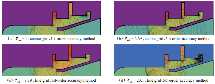
For comparison, in Fig. 2 there are the pressure fields in the calculated region after shock wave inlet into the nozzle of the motor(t=0.01s), obtained by using different numerical methods on different grids. The figure also shows the related calculation times τcalc-relation of the calculation time to the calculation time of the "quickest" variant(time of calculation with first order method on coarse grid).
|
Fig. 2 Pressure fields in the SPRM chamber obtained by various methods on various grids |
We remark that all results in the present paper are illustrative ones and all calculations were made in relative variables so hereinafter we will not put legends in the contour plots to avoid сlutter and extra detalization.
The comparison of the pictures lying on the "main diagonal" of Fig. 2 confirms the well-known conclusion: the use of high accuracy order methods at fine grids gives a more detailed picture of the flow than the use of low accuracy order methods at coarse grids, but obtaining such solutions requires more calculation time (23 times more in our case). However, comparing the figures in another diagonal in Fig. 2 leads to a less trivial conclusion: the use of high accuracy order methods at coarse grids allows obtaining a better solution in less time than using low accuracy order methods at fine grids.
Variants(c, d)are calculated before the end of a launch process(before SPRM starts working at the main mode). The comparison of the calculated data of the main engine parameters with the experimental data is given in Table 1.
|
|
Table 1 Comparison of the main engine parameters |
As we can see, calculations using the low accuracy order method give some underestimation of the values of SPRM parameters in comparison with experiment, and the use of the high accuracy order method gives overestimated values of the parameters. This is because low accuracy order methods have the value of schematic viscosity that is great, which causes unphysical dissipation and, accordingly, the underestimation of the values of the parameters. To improve the data obtained with the use of high accuracy order methods, it is necessary to take into account molecular and turbulent conduction processes in the initial system of equations.
3 Reduction in spatial dimension of the problemIn SPRM family, there is a fairly extensive subclass of long engines, the length of which is much larger than the diameter. In this case, it is possible to reduce the calculation time significantly by reducing the spatial dimension of the problem being solved. To achieve this, we have to consider the problem of the full cycle of hypothetical SPRM operation simulation, the configuration of which is shown in Fig. 3.

|
Fig. 3 General configuration of long SPRM |
The total length of the simulated engine is 3.6m, the shell diameter is 0.4m. The properties of combustion products and solid propellants are given below.
Cp = 1945J/(kg∙K)—combustion products specific heat at constant pressure
Cv = 1662J/(kg∙K)—combustion products specific heat at constant volume
ρsp = 1730 kg/m3—density of solid propellant load
Tcp = 3200K—temperature of the combustion products
Tign = 1000K—ignition solid propellant temperature
asp = 0.3m2/s—thermal diffusivity of solid propellant load
To develop the calculation models of the motion of combustion products, we use a system of equations for the dynamics of nonviscous non-heat-conducting gas written conservatively in a Cartesian coordinate system
| $ \begin{array}{l} \frac{{\partial \rho }}{{\partial t}} + {\rm{div}}\left[ {\rho V} \right] = 0\\ \frac{{\partial \rho {v_j}}}{{\partial t}} + {\rm{div}}\left[ {\rho {v_j}V} \right] + \frac{{\partial \rho }}{{\partial {x_j}}} = 0,j = 1,2,3\\ \frac{{\partial E}}{{\partial t}} + {\rm{div}}\left[ {HV} \right] = 0 \end{array} $ | (4) |
To determine the heating of solid propellant, the heat conduction equation is used, which, taking into account the axial symmetry of the problem and the parameter constancy of solid propellant, has the following formula
| $ \frac{{\partial T}}{{\partial t}} = a\left( {\frac{{{\partial ^2}T}}{{\partial {r^2}}} + \frac{1}{r}\frac{\partial }{{\partial r}}\left( {r\frac{{\partial {T_i}}}{{\partial r}}} \right)} \right) $ | (5) |
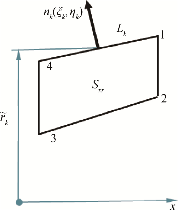
For the discretization of the system of equation(4) with respect to the spatial coordinates, the control volume(СV)method is used. While constructing a spatially-dimensional(two-dimensional in our case) model (2D model), the calculation domain is divided into structured CVs of the circular shape of a tetragonal(in the plane (x, r))cross-section(see Fig. 4)
|
Fig. 4 Cross section of control volume in two-dimensional simulation |
After integrating the system of equation(4)on the obtained CV, we obtain a semi-discrete form(6)(the equations are written for each CV, CV indices are not indicated for a less lengthy formula)
| $ \begin{array}{*{20}{c}} {\frac{{\partial U}}{{\partial t}}V + \sum\limits_{k = 1}^4 {{{\tilde r}_k}{L_k}\left( {{\xi _k}{\mathit{\boldsymbol{F}}_k} + {\eta _k}{\mathit{\boldsymbol{G}}_k}} \right)} = {s_{xr}}\mathit{\boldsymbol{S}}}\\ {\mathit{\boldsymbol{U}} = \left( \begin{array}{l} \rho \\ \rho u\\ \rho v\\ E \end{array} \right),\mathit{\boldsymbol{F}} = \left( \begin{array}{l} \rho u\\ \rho {u^2} + p\\ \rho vu\\ uH \end{array} \right),\mathit{\boldsymbol{G}} = \left( \begin{array}{l} \rho v\\ \rho uv\\ \rho {v^2} + p\\ vH \end{array} \right),\mathit{\boldsymbol{S}} = \left( {\begin{array}{*{20}{c}} 0\\ 0\\ p\\ 0 \end{array}} \right)} \end{array} $ | (6) |
To solve the system of equation(6), as in the previous section, we use a difference scheme of the method of join approximants of the fifth order of accuracy [15] in time and space.
To obtain a one-dimensional(1D) model of the combustion products flow in SPRM channel, the system of equation(4)is integrated by CV in the form of a truncated cone with a length Δx obtained by the cross-section of SPRM channel by planes that are perpendicular to the axis of the engine. As a result, the following system of differential equations is obtained for each CV (the index i corresponds to CV number)
| $ \begin{array}{l} \frac{{{\rm{ \mathsf{ δ} }}{\rho _i}}}{{{\rm{ \mathsf{ δ} }}t}}{V_i} + {\left( {\rho uf} \right)_{i + \frac{1}{2}}} - {\left( {\rho uf} \right)_{i - \frac{1}{2}}} = {{\dot m}_i}\Delta {S_i}\\ \frac{{{\rm{ \mathsf{ δ} }}{{\left( {\rho u} \right)}_i}}}{{{\rm{ \mathsf{ δ} }}t}}{V_i} + {\left( {\left( {\rho {u^2} + p} \right)f} \right)_{i + \frac{1}{2}}} - {\left( {\left( {\rho {u^2} + p} \right)f} \right)_{i - \frac{1}{2}}} = \\ \left( {{p_i} + \frac{{\dot m_i^2}}{{{\rho _{{\rm{sp}}}}}}} \right)\left( {{f_{i + \frac{1}{2}}} - {f_{i - \frac{1}{2}}}} \right) - {\tau _w}\Delta {S_i}\\ \frac{{{\rm{ \mathsf{ δ} }}{E_i}}}{{{\rm{ \mathsf{ δ} }}t}}{V_i} + {\left( {uHf} \right)_{i + \frac{1}{2}}} - {\left( {uHf} \right)_{i - \frac{1}{2}}} = \left( {{{\dot m}_i}{h_{{\rm{cp}}}} - {q_{\rm{w}}}} \right)\Delta {S_i} \end{array} $ | (7) |
Here V-CV value, ṁ-the mass input due to burning of the solid propellant, f-the cross-sectional area of the channel, ΔS-the burning area of solid propellant, qw-the heat flow from the combustion products to the solid propellant.
To integrate the system of equation(7), we also use the difference scheme of the method of join approximants of the fifth order of accuracy.
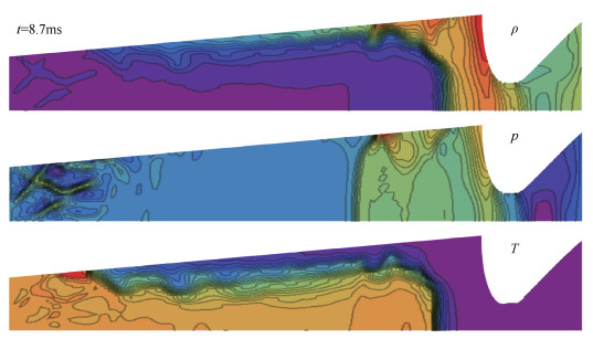
With the help of the 1D-model and the 2D-model (6), the start of SPRM shown in Fig. 3 is calculated. In Fig. 5, the fields of the flow parameters of the combustion products at the wave stage of a starting process(after membrane breaking) obtained from the 2D model are given for illustration.
|
Fig. 5 Fields of flow parameters for 2D simulation of SPRM launch |
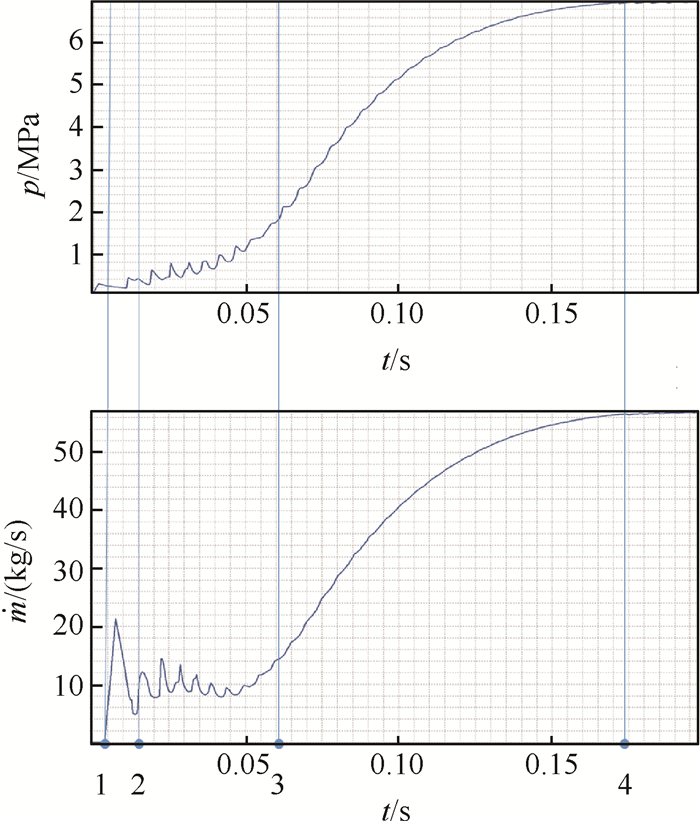
As a result of the calculation, all the main elements of the complex flow of combustion products in SPRM channel are obtained(the shock wave that is reflected from the nozzle entry, contact discontinuity before the nozzle entry, a complex coherent structure in the interaction zone of the flows from the igniter and the burning propellant(see the left area of structural contours of the pressure field)). Fig. 6 shows the graph of the change the bottom pressure depending on the time during the launch, obtained from the 2D model.
|
Fig. 6 Dependence of bottom pressure on time in 2D simulation of SPRM launch |
As we can see, the graphs clearly track the main stages of SPRM launch. There are membrane breaking (point 1, see Fig. 6), start of the ignition of the solid fuel (point 2), total ignition of the solid propellant charge (point 3) and end of burning of the igniter charge (point 4).
The same problem is solved using the 1D-model. The data obtained differs from the data obtained according to 2D modeling by no more than 3.5% with respect to the norm L1, which indicates a high reliability of the data. In this case, it takes 136(!)times less time for obtaining such data. This fact demonstrates great 1D-simulation effectiveness(where possible).
4 Use of physical features of processes at formulation of calculation modelsIt is mentioned that using methods of high accuracy order and, where possible, reducing the dimension of a problem reduces significantly the calculation time. However, even in this case, the calculation of SPRM full cycle takes tens of minutes of physical time. This fact is not always acceptable while designing SPRM. Another way to reduce the calculation time while simulating SPRM is to use the physical properties of the processes that take place during SPRM operation. It is known that for SPRM there are three time scales: τchem-the characteristic time of chemical processes, τfluid-the characteristic time of gas dynamic processes, τsurface-the time of the burning surface change and the volume of SPRM combustion chamber. These times are related by the following inequalities
| $ {\tau _{{\rm{chem}}}} \ll {\tau _{{\rm{fluid}}}} \ll {\tau _{{\rm{surface}}}} $ | (8) |
The first of the inequalities has been used while designing SPRM for a long time: instead of a detailed review of chemical processes, researchers use empirical relationships for the burning rate. The most often used is the combustion power law that is mentioned above.
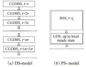
We investigated the possibility of using the second inequality(8)using the example of constructing a onedimensional calculation model of SPRM, described in Section 2 of this work(see Fig. 3). Two calculation models of SPRM processes are constructed: one model deals with a direct physical simulation of the processes in SPRM(DS model), the other one(PS model)touches upon the breaking according to the physical processes and taking into account the second inequality(8). During the formulation of both models, the same initial equations and numerical methods are used as in Section 2.
The calculation according to the DS-model(see Fig. 7(a))consists of the sequential mode of time steps, each of which is engaged in simultaneous solution of equations of propellant burning and combustion products dynamics. In this case, time step τ size is taken from the constraints resulting from the equations of the combustion products dynamics (Courant number Cu = τVmax/h should be less than 1).
|
Fig. 7 Schemes of calculation models CGDBS—Coupled Gas Dynamic and Burning System Solving step, BSS—Burning System Solving step(with frozen GD parameters, τb>>τ), GDS—Gas Dynamic System Solving step(with frozen burning surface and chamber's volume) |
When performing calculations based on the PS model, the calculation at each time step is carried out in two stages: the first stage deals with determining the burning surface change and SPRM chamber's volume for a sufficiently long period of time τb>>τCu, while the second one focuses on the calculations of the combustion products parameters in SPRM channel with a new unchanging form of a combustion chamber and combustion surface.
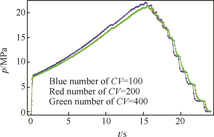
Fig. 8 shows the bottom pressure curves obtained as a result of calculating the full cycle of the model SPRM operation according to the DS model using different numbers of CV.
|
Fig. 8 Dependence of bottom pressure on time while simulating the cycle of SPRM operation according to the DSmodel |
As we can see, with an increase the CV numbers, the difference between solutions decreases, which indicates the convergence of the methodology. The estimation of convergence rate gives approximation order 3.2.
When using the PS model, besides Courant number, another parameter of the calculation model appears-the ratio of the time step size while solving the combustion surface change equation to the discretization step with respect to a spatial coordinate
| $ a = \frac{{{\tau _{\rm{b}}}}}{h} $ | (9) |
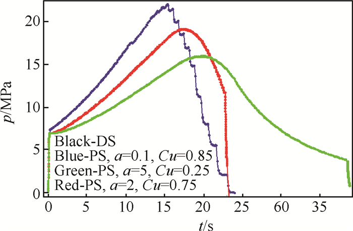
Fig. 9 shows the dependency graphs of bottom pressure on time, obtained from the PS model at different values of the parameters (Cu, a).
|
Fig. 9 Dependence of bottom pressure on time while simulating the cycle of SPRM operation according to the PS model at various values of model parameters |
As it is obvious, at small values a different model solutions are not distinguishable (the black and blue curves in Fig. 9), but there is no significant decrease in the calculation time. While using large values a, the data obtained qualitatively and quantitatively differs from the data obtained according to the DS model(the green and red curves in Fig. 9).
To determine the optimal values of the parameters (Cu, a), the following minimization problem is solved: such values (Cu, a) are determined at which the calculation time reduces to a minimum
| $ {t_{{\rm{cale}}}} \to \min $ | (10) |
Under the following constraints
| $ {\left\| \varepsilon \right\|_C} < 0.05,Cu \in \left[ {0.1,1} \right],a \in \left[ {0.1,5} \right] $ | (11) |
Here ‖ε‖C is an estimated relative deviation of the solution obtained according to the PS model and obtained according to the DS-model in the norm of space C.
As a result, the following values of the optimized parameters are obtained
| $ Cu = 0.85,a = 2.03 $ | (12) |
Table 2 shows the values of the relative calculation time while simulating the processes in SPRM using different approaches.
|
|
Table 2 Relative calculation times at simulation SPRM |
As is obvious, the use of the PS-model makes it possible to reduce the calculation time a lot even in comparison with the 1D DS-model, while comparing with direct simulation using the 2D model, saving of time becomes even more significant(it should be noted that in our calculations the calculation time unit corresponds to 10 minutes, one calculation flow is used). Finally, a similar splitting can also be used for multidimensional calculations.
5 ConclusionsThe paper presents the findings of an investigation of various ways to improve the time efficiency of calculation models of SPRM processes. The conclusions are as follows:
(1) The use of numerical methods of high accuracy order, the reduction in a spatial dimension of the problem and the use of the physical features of a simulated process make it possible to reduce the time required for the calculations by orders of magnitude. The use of such approaches will significantly speed up the process of SPRM preliminary design.
(2) Multidimensional models need to be used in the design-primarily for setting the 1D models and determining the parameters of the final designed SPRM before fire test operations.
Acknowledgments This work is based on the author's report on 37th Technical Seminar of the Aerospace Powerplant Technology Information Society and First International Joint Conference of Aerospace Propulsion (Xi'an, China, 2016). The author is grateful to the sponsors of the conference for financial support and warm welcome at the conference.
| [1] |
Havlucu M O, Kirkkopru K. Numerical Simulation of Flow in a Solid RockeL MoLor: CombusLion Coupled Pressure Dependent Regressive Boundary[J]. International Journal of Engineering Science Invention, 2017, 6(3): 54-65.
(  0) 0) |
| [2] |
Attili A, Favini B, Di GiacinUo M. Numerical Simulation of Multiphase Flows in Solid Rocket Motors[R]. AIAA 2009-5507.
(  0) 0) |
| [3] |
Yu Y, Liu S Y. Simulation of Two Phase Viscous Flows in a Solid Rocket Motor[C]. Shanghai: New Trends in Fluid Mechanics Research Proceedings of the Fifth International Conference on Fluid Mechanics, 2007.
(  0) 0) |
| [4] |
Gueyffier D, Roux F X, Fabignon Y, et al. High-Order Computation of Burning Propellant Surface and Simulation of Fluid Flow in Solid Rocket Chamber[C]. Cleveland: AIAA/ASME/SAE/ASEE Joint Propulsion Conference, 2014.
(  0) 0) |
| [5] |
WANG Jian-ru, HE Guo-qiang, LI Qiang, et al. Numerical Analysis of Flow Instability in Segmented SRM[J]. Journal of Propulsion Technology, 2013, 34(1): 95-100.
(  0) 0) |
| [6] |
Fabignon Y, Dupays J, Avalon G, et al. Instabilities and Pressure Oscillations in Solid Rocket Motors[J]. Aerospace Science and Technology, 2003(7): 191-200.
(  0) 0) |
| [7] |
Guéry J F, Ballereau S, Franck G. Thrust Oscillations in Solid Rocket Motors[R]. AIAA 2008-4979.
(  0) 0) |
| [8] |
YANG Shang-rong, LIU Pei-jin, WEI Xiang-geng, et al. A Study of Analysis Method for Hydrodynamic Stabilities of Solid Rocket Motors with Side-Induced Flow-[J]. Journal of Propulsion Technology, 2013, 34(7): 925-931.
(  0) 0) |
| [9] |
Dotson K W, Koshigoe S, Pace K K. Vortex Shedding in a Large Solid Rocket Motor without Inhibitors at the Segment Interfaces[J]. Journal of Propulsion and Power, 1997, 3(2): 197-206.
(  0) 0) |
| [10] |
Najjar F M, Ferry j P, Haselbacher A, et al. Simulations of Solid-Propellant Rockets: Effects of Aluminum Droplet Size Distribution[J]. Journal of Spacecraft & Rockets, 2015, 43(6): 1258-1270.
(  0) 0) |
| [11] |
Attili A, Favini B, Giacinto M D, et al. Numerical Simulation of Multiphase Flows in Solid Rocket Motors[C]. Denver: 45th AIAA/ASME/SAE/ASEE Joint Propulsion Conference and Exhibit, 2006.
(  0) 0) |
| [12] |
LITeng, FANG Shu-zhou, LIU Xu-hui, et al. Numerical Study on Two Dimensional Adiabatic Microscale Combustion Model for Solid Propellant[J]. Journal of Propulsion Technology, 2016, 37(12): 2385-2393.
(  0) 0) |
| [13] |
Kaili Zhang, Chou S K, Simon S Ang. MEMS-Based Solid Propellant Microthruster Design, Simulation, Fabrication, and Testing[J]. Journal of Microelectromechanical Systems, 2004, 13(2): 165-175. DOI:10.1109/JMEMS.2004.825309
(  0) 0) |
| [14] |
Bucharsky V L. Two-Step Difference Schemes of ihe Method of Approximants for Solving Quasilinear One-Dimensional Hyperbolic Equations[J]. Eastern-European Journal of Enterprise Technologies, 2013, 4(62): 34-38.
(  0) 0) |
| [15] |
Bucharsky V L. Finite-DiHerence Schemes of the Method of Approximants for Solving Multidimensional Quasilinear Hyperbolic Equations[J]. Eastern-European Journal of Enterprise Technologies, 2013, 4(63): 64-67.
(  0) 0) |
 2018, Vol. 39


